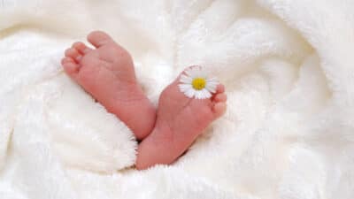
100 Best Innocent Smile of a Baby Quotes for boys and girls
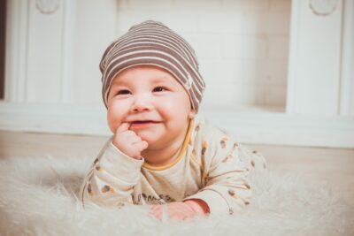
Innocent Smile of a Baby Quotes: Babies are the most heavenly gift of God to us humans. They are just so adorable with their cute innocent smiles. There is no better feeling in the world than what you feel after making a baby smile. It’s undoubtedly the most beautiful thing in the world. Nothing in the world is good enough that can describe the feeling that one feels when he sees a baby’s smile. Baby smile quotes are one way of expressing these feelings.